Build a pocket fencing body cord and weapon tester
A rechargeable, pocket-sized go/no-go tester for three-prong body cords and foil and épée weapons. Two lamps, no programming, a few inexpensive parts and a 3D-printed case.
Prototype. The design and documents are complete; the first physical build is in progress.
The printed case files will be published once a real build confirms the jack fit.
How it works
The green lamp sits across the A and B lines of the cord, the red lamp across B and C. Because B is shared, two lamps are enough to check all three wires. How you plug in picks the test:
| Both ends plugged in (continuity) | Means |
|---|---|
| both lit | All three wires are good |
| red only | A line is broken |
| green only | C line is broken |
| both dark | B line is broken |
| Only the first end plugged in (shorts test) | Means |
|---|---|
| both dark | No shorts found |
| green lit | A is shorted to B inside the cord |
| red lit | B is shorted to C inside the cord |
Weapons: plug a known good cord into the tester with the weapon on the far end. A foil at rest lights red and goes dark when the tip is pressed. An épée at rest is dark and lights green when the tip is pressed.
What it does not do: it checks continuity, not resistance. FIE limits are 2 ohms for a foil or
épée, 1 ohm for a sabre or a body cord wire, and 5 ohms across a lamé, so a cord that passes here can still be too
resistive for a scoring box. A short between the A and C lines alone is not detected (A and C sit farthest apart in the plug, so it is rare).
What you need
- 6 panel-mount 4 mm banana jacks (all three plug pins are 4 mm by FIE rule)
- 1 protected TP4056 lithium charging board (USB-C) and 1 18650 cell with a holder
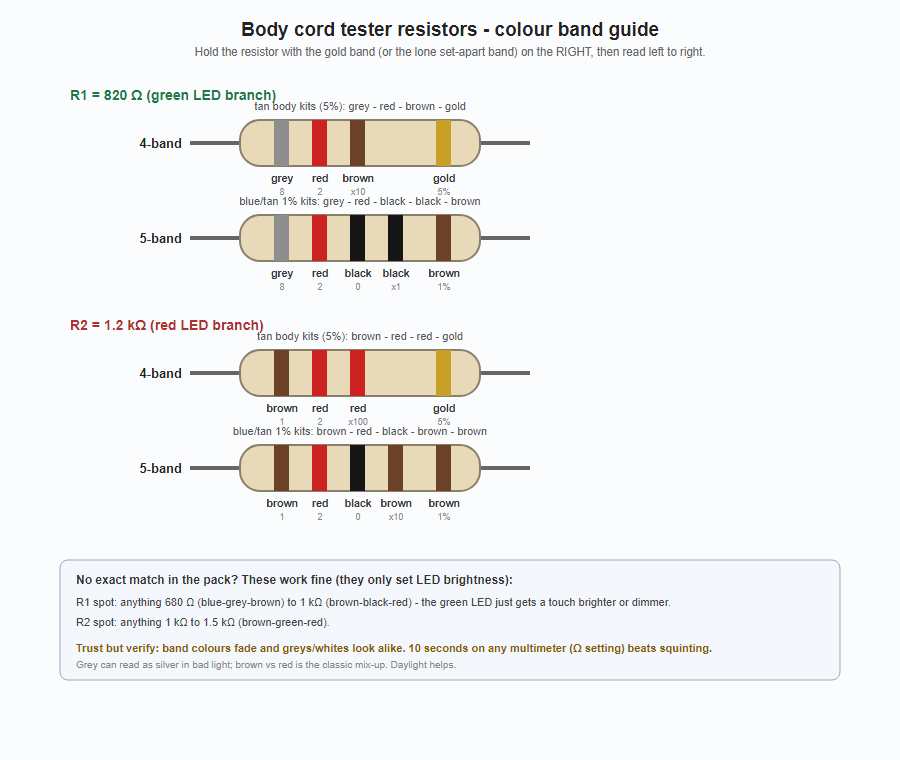
- 1 green and 1 red 3 mm LED, an 820 ohm and a 1.2 k resistor, a 100 nF capacitor
- A brass M3 screw for the lamé clip post, M2 screws for the lid, thin hookup wire
- A soldering iron and a multimeter
The printable store shopping list has every part in plain language, one page per build.
Battery safety: use the protected charging board and a proper cell holder, never solder directly to the
cell, and take power from the board's OUT pads so the protection stays in circuit.
Build order
- 3D print the jack spacing coupon and check a real body cord plugs into your jacks.
- Wire the circuit, following Doc 05 (picture-style, numbered wires) alongside Doc 01.
- Run the checks in Doc 03 against a cord and weapon you know are good.
Downloads
| Complete build pack (Docs 00, 01, 02, 03 and 05 in one PDF) | PDF · 365 KB |
| Doc 00: overview and parts list | PDF · 113 KB |
| Doc 01: circuit and schematic | PDF · 113 KB |
| Doc 02: sockets and pin mapping | PDF · 95 KB |
| Doc 03: how to test cords and weapons | PDF · 94 KB |
| Doc 05: picture-style wiring diagram (start here if schematics are new to you) | PDF · 143 KB |
| Jack spacing test coupon (3D print this first) | STL · 151 KB |
| Coupon source (OpenSCAD, adjustable hole size) | SCAD · 1 KB |
| Resistor color band guide | PNG · 55 KB |
| Store shopping list, one page per build (no links) | PDF · 142 KB |
| Sourcing sheet with online buy links (checked Aug 2026) | PDF · 206 KB |